RayVerse® 10KP
Core technology: Spherical near-field testing (near- and far-field conversion)+ tight-field fast calibration

Product Description
During the development and production of the large–scale phased array antenna, phase and amplitude calibration is necessary, as well as the multi–beam patterns measurement. RayVerse 10KP supports rapid calibration and testing of large–scale phased array antenna from S-band to W-band.
GTS invented the integrated rapid calibration and testing system of a phased array, which consists of two subsystems: A) Phased Array Calibration Subsystem (Planar near–field), which includes low frequency link and spread spectrum link on the DUT side, as well as low–frequency link and frequency conversion link on the planar scanning probe side. This system consists of test instruments, frequency converters, switches, amplifiers, etc, to achieve the function of the phased array calibration. B) Phase Array Testing Subsystem (Spherical near–field): It includes the low–frequency link and spread spectrum link on the DUT side, as well as low frequency link and frequency conversion link on the arc scanning probe side. This system consists of test instruments, frequency converters, switches, amplifiers, etc, to achieve the testing functions of phased array antenna pattern, EIRP and G/T value, etc.
Product Features
Failure diagnosis capability
The system has array element diagnostic functionality. Through rapid element channel calibration, the amplitude and phase information can be obtained, and any relevant parameters can be identified and removed. By establishing an array model based on the phase array element coordinates, the graphic channel information can be presented, as
shown below.

Unit diagnostic effect (part of the unit is closed in the center area on the right)
Strong far–beam testing capability
A spherical near–field testing system is not restricted by scanning range, theoretically, it supports any range scanning across the entire spherical surface. So it can test antennas of any type and any beam directions. Moreover, its testing accuracy will not deteriorate for far–beam.
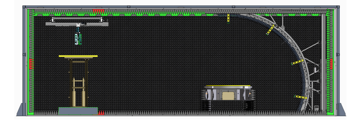
Easy testing setup
This chamber has the reflector installed on the top, system performs the spherical scanning with the swing arm. DUT can be easily laid flat on a one–dimensional azimuth positioner. Moreover, unlike planar near–field testing that requires precise positioning of the DUT, this approach significantly reduces the pre-test setup time and simplifies the testing procedure.
Fast Calibration Speed
With the spherical near–field method, the testing speed can be improved in the following two aspects:
(1) Frequency point, multi-channel, wave a quick test
Typically, an active phased array antenna has multiple frequency points, multiple test channels, and multiple beam directions. Using a conventional measurement system, each antenna state needs to be tested separately, resulting in low testing efficiency. This system achieves high testing efficiency through real–time interaction between testing software and the phased array beam controller, combined with multi–channel switches
and multi–frequency sampling of instruments, realizing full testing automation under microsecond–level timing control. The system can complete testing for thousands of beam directions with just a single 3D scan. Compared to the conventional testing method, its testing efficiency is improved by dozens of times.
(2) Simplified Setup, No need for precise positioning
Spherical near–field system utilizes a swing arm to perform spherical scanning, DUT is only required to be placed on a one–dimensional azimuth positioner. This setup is convenient and can be completed in a few minutes. Additionally, during the spherical
near-field scanning, DUT can be roughly placed within the quiet zone, eliminating the precise alignment. Estimate a minimum spherical diameter D that can enclose the DUT, calculate the required sampling density using the formula λ/D and scan, finally perform the near-field to far-field transformation. Compared to planar near–field testing, this system’s DUT installation process can save several hours.
High safety factor
(1) System components are selected to meet the corresponding national standards
(2) Thermal imaging is used for 7 x 24 hour monitoring and real-time reporting of monitoring data
(3) The system is equipped with smoke and dust detection capability, detecting the smoke and dust concentration in the system in real time and keeping records at the same time, and automatically alarming when the smoke concentration is detected to exceed the standard.
High calibration accuracy
(1) Sampling accuracy won’t deteriorate as the scanning range expands
In a spherical near–field testing system, the test probe maintains alignment with the DUT throughout the scanning process. Theoretically, sampling accuracy at any angle is consistent. Unlike the planar near–field system, the probe may lose alignment with the DUT as the scanning range expands, leading to changes in the radiation pattern and degradation in cross–polarization, resulting in deteriorated testing accuracy.
(2) Cutting–edge corrugated horn antenna with wide–angle and low cross–polarization
GTS has developed and designed wide–angle, low cross–polarization corrugated horn feeds.Its cross–polarization can maintain -40dB within an angular range of ±20°.Its phase fluctuations between the E-plane and H-plane are less than 5° within an angular range of ±50° , with excellent symmetry characteristics.These two features represent cutting–edge performance.
The wide bandwidth and high phase stability ensure minimal phase fluctuations in the quiet zone. The high edge illumination level (wide beamwidth) results in reduced amplitude variations in the quiet zone. The integrated design with absorbers (its outer surface covered by absorbing material) ensures low RCS characteristics of the feed horn.

Comparison of planar near-field, tight-field and this solution

Wide angle low cross polarisation corrugated horn probe
